Replica rolls are created using equipment and software produced by the Rollscanners internet group. This uses an optical scanner to 'read' the original roll, and software to process this into a new master roll that exactly locates every punch in the original. The replica roll will then contain exactly the same pattern of punches as the original roll, and will play the same. This is the "holy grail" of roll copying, a milestone in the history of roll making. The following article describes how it was achieved, and who did it.
Perfect roll copying with the Mk3 BT roll scanner
Julian Dyer, July 2003
Roll scanning has made significant advances in recent years, applying technology to possibly the most obvious yet hardest of all conservation and preservation topics, the replication of aging and disintegrating piano rolls. This article describes how Richard Stibbons’ Mk3 BT roll scanner circuitry has succeeded in the ‘holy grail’ task of creating a perfect replica piano roll.
 Summary: A Spencer Chase / Richard Stibbons scanner equipped with Stibbons Mk3 BT
electronics and a DynaImage CIS array has been refined to give sufficient
accuracy for a roll master can be extracted from the resulting scan image. The
development process has identified sources of inaccuracy within the scanner and
generally-applicable techniques to eliminate these errors. Exact replica rolls
have been perforated from these masters, demonstrating that the whole process is
viable.
Summary: A Spencer Chase / Richard Stibbons scanner equipped with Stibbons Mk3 BT
electronics and a DynaImage CIS array has been refined to give sufficient
accuracy for a roll master can be extracted from the resulting scan image. The
development process has identified sources of inaccuracy within the scanner and
generally-applicable techniques to eliminate these errors. Exact replica rolls
have been perforated from these masters, demonstrating that the whole process is
viable.
Roll scanning and roll master re-creation
Roll scanning is the process of reading a music roll into a computerised form that can be used for any purpose, such as cutting new rolls or operating old or new instruments directly. This uses the same technology as domestic flatbed scanners, hence the term roll scanner. The ubiquity of computers makes scanning fundamental to the preservation of rolls of all types, as well as providing the basis for secondary activities such as operating instruments directly.
Roll master re-creation is the process of understanding how the roll was originally manufactured so that errors arising from the scanning are removed and the computer works to the same accuracy as the original perforators in the roll factory. This allows exact replica rolls to be made, and maximises the accuracy of any secondary activity.
Reasons for replicating the master roll
Replication of the original master from which a perforated paper roll was created is the highest aim of roll scanning. Roll masters are not literally replicated, because they were originally large cardboard rolls, but re-created in a computerised form. The rationale is that if you start with the master in this form you can do anything with the music – cut new rolls, operate player pianos fitted with electronic valves, or simulate a performance for playing on modern instruments – all without introducing any errors.
Why is this so? The simple answer is that a roll is punched in fixed rows, so a punch will occur only in one row or the next, but never in between: the roll is a digital storage medium. Scanning simply counts the distance from the start of the roll to each note event, giving an analogue, and hence inaccurate, representation of the roll. If instead you count in rows, you have an exact representation of the original roll – a perfect digital copy. This can be done by applying knowledge about the original roll’s creation to the scan.
Once the master has been recreated, you have perfect and complete knowledge about the roll, and anything you want to do after this can be done to the accuracy of the original roll. If you stick with the analogue version all its timing errors are carried through to whatever you do with it, and frequently amplified along the way. This is particularly true when making recut rolls, where imposing the punch-row spacing of the perforator over the (different) row spacing of the original roll causes surprisingly obvious and audible errors. However, even analogue uses of the scan, such as operating instruments directly, benefits from the recreated master because of the way it removes timing errors from the basic scan, and in so doing allows the accuracy of the scanner itself to be calibrated.
Historical overview
Roll scanning itself is not of major significance – it simply adds optical technology to the pneumatic, electrical and mechanical technologies previously used to extract data from perforated paper. The ability to store the extracted data on electronic media marked the start of the modern era of scanning, but did little more than act as a substitute for the paper roll. The most familiar such system is the Marantz Pianocorder, but at least two systems were produced, by Wayne Stahnke and Peter Phillips, to operate pneumatic pianos.
From having the performance in ‘streaming’ form on a tape to extracting the note events into a list in a computer is a fairly small step. Such computerisation of the scanned data adds the ability to edit and manipulate it. The key advance we are concerned about here is the manipulation that converts the analogue scan data to a replica of the perforation master.
The first serious and sustained roll master replication exercise was probably that of Wayne Stahnke, who described his by-then completed methods in the Mechanical Music Digest in March 1996, and used them to practical advantage in his Rachmaninoff-Bösendorfer CDs. He started with a pneumatic roll reader (from the mid 1970s, for the IMI Cassette Converter system) and later moved to an optical system. He has been offering commercial scanning and roll master re-creation since the mid 1990s.
Within UK Player Piano Group circles the topic of recreating roll masters was already well established by 1996. Rex Lawson had raised the topic as part of his work developing a perforation-level roll editor software suite for his Perforetur rolls, and the topic was publicly discussed in the PPG bulletin during winter 1994/5 when Rex explained precisely why rolls should be copied punch-for-punch, digitally.
Richard Stibbons started his roll-scanning attempts in the mid 1990s, and described his progress in PPG article “The PC Pianola” in December 1995. Soon afterwards he adopted the master replication idea, described very thoroughly in September 2000. This led directly to the launch of the internet ‘Rollscanners’ group in February 2001.
The aim of this group has been to focus and publicise scanning efforts worldwide, encouraging sharing of progress and knowledge, a radical shift from the earlier essentially private attempts.
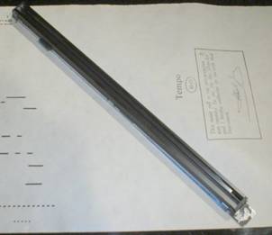
The Rollscanners Mark 3 BT scanner
The scanner used during this evaluation in based on a prototype chassis and paper transport built by Spencer Chase. The project described here involved adding the imaging device and driver electronics, and interpreting the resulting scans.
The rollscanners group identified the Dyna Image DL408 CIS (Contact Image Sensor) array as a suitable device for taking the image of the roll. This is the type of device used in older A3 photocopiers and flat-bed scanners. Although A4 scanners (8.5” long) are commonplace, they are not wide enough to deal with a piano roll. Longer arrays are far less common and much more expensive. Bob Pinsker obtained some 50 of these arrays from the supplier, their entire remaining stock, and redistributed them at cost (so secondhand Mustek A3EP scanners are the only ready source for them now).
 The
advantage of the CIS array is that it is small and totally self-contained,
using a series of rod lenses to transfer the image to the sensing elements that
span the entire width of the array. Its disadvantage is a very low depth of
focus of only 0.3mm which, as explained later, has caused problems. Newer CCD
(Charge Coupled Device) technology as used in digital cameras is more complex
if only for the fact that the sensor is tiny and requires an optical system to
focus the image onto it, although it gives much greater depth of focus. CCD
scanning has not been tried yet.
The
advantage of the CIS array is that it is small and totally self-contained,
using a series of rod lenses to transfer the image to the sensing elements that
span the entire width of the array. Its disadvantage is a very low depth of
focus of only 0.3mm which, as explained later, has caused problems. Newer CCD
(Charge Coupled Device) technology as used in digital cameras is more complex
if only for the fact that the sensor is tiny and requires an optical system to
focus the image onto it, although it gives much greater depth of focus. CCD
scanning has not been tried yet.
Although the Rollscan-1 board was designed by May 2001 and shipped the following December, it has so far taken over 18 months to overcome various faults. To keep the project moving, Richard Stibbons revisited his older and simpler scanner design in light of experience, looking to implement a basic version of the scanner board. In December 2002 he produced his “Mark 3 Bit Twiddler” circuit design, which was duly converted into a real circuit board with the assistance of Terry Smythe (with connectors made by Albert De Boer).
Richard fitted the new circuit board to his scanner, and it was immediately up and working. The earlier Stibbons/Chase scanners produced images of 180 lines per inch along the roll, but the Mk3 produces images of 360 lpi along the roll and 300 lpi across it. The simple board design limits the image to black and white, a clipper adjustment on the board controlling the level of the boundary between black and white. The board plugs into the parallel port of a PC: the standard PC ports being rather slow, a LAVA parallel-PCI port card was identified as the fastest available (some 3 times quicker than the PC’s own port). With this a roll can be scanned at some 2.5 feet per minute, and a speed-doubler prototype is now being evaluated.
The software creates an image of the roll in a special ‘CIS file’ format. This keeps file sizes down by using a compression technique only applicable to black and white images, storing only the points in each row where the image changes from black to white or vice versa (run length encoding).
Although flat-bed scanners always use reflected light, roll scanners tend to give better results with transmitted light that separates holes from dirt on the roll. CIS arrays come complete with a built-in cold-cathode fluorescent light, which has the vital flicker-free behaviour. The scanner works hundreds of times per second, so can see the flicker of a mains-frequency tube. Modern starter-free fluorescent lights are suitable because they operate the tube at a very high frequency: here a 12” light from a DIY store is used, the light level matched to the scanner sensitivity with neutral-density film.
As reported more fully below, this system has eventually been proven sufficient to extract the full perforation matrix from typical Ampico and Duo-Art rolls, which are perforated around 30 rows per inch. The scan-decoding software is now limited by manufacturing imperfections in the rolls themselves, and not by any deficiencies of the scanner. Given that there is no further information to be extracted from the roll once the matrix is identified, nothing will be gained from increased scanner resolution. The simple Mk3 design therefore does all that is required for a successful scanner.
Future developments may involve greyscale or colour scans, and faster scanning. Greyscale offers more information about the edges of perforations and allows their position to be tracked in software, and would make identification of the perforation matrix easier. Colour could identify printed information such as words or dynamic/tempo markings. All of these would require major software changes.
Because this scanner is a prototype and not a model for others, many specific details of its design have not been given here because they shouldn’t be copied. Details of the Mk3 circuit can be located at www.iammp.org/scannerdesign.htm.
Extracting the roll master
In early March 2003, Richard loaned me his now-complete prototype scanner to try various hardware and software ideas, particularly to see whether it would be possible to improve its accuracy to enable roll masters to be replicated from its scans.
Interpreting the scan
Simply building a scanner is not enough. You need to be able to interpret the results of the scan, which is simply a black and white image of the roll. This being a computerised operation, a computer programmer is required. Richard has supplied a basic program that performs an analogue interpretation of the CIS file, but the aim of the project is to perform a full digital interpretation.
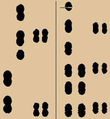
 For
this, Rollscanners is fortunate to have the services of Anthony Robinson: he has
been working for a while on a program that places imaginary individual punches
on top of the scanned image, thereby working out which punches were used to
create the original roll. The approach taken for this task has been, in effect,
to place a grid over the scanned image: a perforation can occur only on the
crossing points on the grid. The black fringes around the punches in the sample
arise from the fuzzy edges of the image, and the white dots show the grid.
For
this, Rollscanners is fortunate to have the services of Anthony Robinson: he has
been working for a while on a program that places imaginary individual punches
on top of the scanned image, thereby working out which punches were used to
create the original roll. The approach taken for this task has been, in effect,
to place a grid over the scanned image: a perforation can occur only on the
crossing points on the grid. The black fringes around the punches in the sample
arise from the fuzzy edges of the image, and the white dots show the grid.
In any roll, this grid can be expected to be distorted for various reasons, such as unstable paper dimensions, physical damage, or manufacturing errors. On top of this are any distortions that arise from the scanner itself. A vital facility of the software is to cope with these distortions in order to identify the underlying grid, so that a perfectly regular master can be extracted from the irregular image. This converts the original fuzzy and irregular image to a crisp and completely regular one. The distortions in the grid necessary to achieve this reflect the distortions in the scanned image, and in principle each can be assigned to a particular cause. A fuller description of this software will hopefully follow when it is a more complete form.
Errors arising from the scanner
Initially, the scans proved to be very hard to match to a grid, because there were numerous sudden shifts. These were not the type of errors expected to arise because of paper distortion, which is a fairly gradual and smooth process. The sudden and frequent discontinuities were therefore likely to arise from a problem within the scanner.
Capstan drive slippage
It was observable that from time to time the paper stopped moving because of slippage in the capstan drive system. It was quite probably slipping microscopically rather more often. This system has a hard rubber roller (the capstan) driven by a stepper motor synchronised to the scanning software, a weighted pinch wheel pressing the paper against the capstan so that friction moves the paper. By progressively increasing back tension until roll slippage was induced it was observed that slippage occurred for a short while at the same point of every capstan rotation, indicating an uneven spot. The substitution of a softer pinch roller, tape recorder style, stopped the obvious slippages by improving contact with the capstan, and within reason heavier weights can be applied until contact is maintained at the weakest spot.
Focus errors
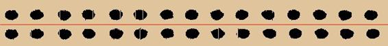
Eliminating slippage did not remove all the glitches in the image. A sample can be seen in this image showing two separate scans of the same roll, with an obvious distortion of the fifth slot from the left yet the images realigning nearly immediately. All the longer slots are two punches long so should appear the same size, which they obviously do not. This sort of timing error is highly unlikely to arise from slippage, because overall the images are of the same length, and there is little chance that each scan would slip precisely the same amount yet at different places. More significantly, the errors were not consistent across the roll.

Observing the paper as it passed over the CIS array, held flat by bars at either side but unsupported for about an inch in the middle, it was obvious that it was bobbling up and down in small patches independently across the roll as it moved across the array. This is a serious problem, because of the CIS array’s 0.3mm depth of focus. Anyone who has used an old-fashioned photocopier will recall just how rapidly the image becomes unreadable at points where the paper curls up – the same was happening to the roll image.
The Mk3 board converts the scan into a black-and-white image, so at some point in the change between dark (no hole) and light (hole) the electronics flips from ‘on’ to ‘off’. If the image goes out of focus, the transition becomes spread across a greater distance, and hence there is more latitude for the position where the ‘edge’ appears to be. The exact effect is determined by the clipper setting on the scanner. The diagram compares the same slot in- and out-of-focus. The nature of the timing errors being observed strongly suggested this was the cause.
 |
This is an important point: in black-and-white scanning, a vertical movement of the paper manifests itself as an unknown horizontal movement of the position of the punch edge – which is exactly the same as a timing error! Loss of focus cannot be observed directly in a B&W image, and it’s easy to miss the effect unless using a tool such as the master recreation software.
All the scanners I have seen have illustrations of have adopted a similar paper path, flattening the paper over the scan array. This does not reflect the way that original player systems worked, and shows a lack of thought about the physical nature of the material being handled. Paper is stored in a curved form, and naturally adopts this shape when unrestrained. It takes energy to flatten the paper, which behaves as a spring that stores this energy. As with any physical system, the paper will adopt the least-energy position at all times, this being its familiar curved shape. In an unsupported design, as the paper passes over the scan array it always tries to curl up, and how far it manages to curl depends on the perforation pattern and the uneven physical state of the paper, so there is a persistent shifting and rippling of the paper as it moves.
Flattening the paper is therefore inviting it to spring up and down, and introduce errors into the scan! Although some builders have tried to use restraining devices to hold the paper flat, this is really introducing one undesirable feature to overcome another. A more logical approach altogether is to leave the paper in its curved form as it passes over the scanner, so giving it the least possible inclination to move. This does away with the need for any restraints, and is also rather kinder to the paper.

The scanner was accordingly dismantled and a trial curved paper path created from a length of plastic guttering from the domestic scrapheap, with a narrow slot cut in it for the array. This fortuitously proved to have exactly the right thickness so that the focal point of 2.5mm above the top of the CIS casing coincided with the surface of the plastic when the array was mounted directly on the lower surface: the height of the moulding also gives the right paper path without having to adjust the original paper transport.
This low-tech approach proved to be remarkably successful, and the timing glitches pretty well vanished – scanning the same roll time and time again gave the same results. A sample of the worst error from a duplicated scan is shown below. It’s hard to tell the difference even at this scale, and this is the worst in the roll. All very satisfactory, a victory for some basic physics theory and engineering!
Azimuth errors
Another problem that had been observed in some rolls was a rapid change in azimuth, the angle of the paper’s passing across the array. While rolls do wander from side to side, which must mean a gradual change of azimuth, this is a relatively gradual process. The scans showed this happening over the space of a few inches, so this was presumably a scanner problem rather than one on the roll itself.
The obvious cause of this was the pressure bar (on the left in the picture) which in this particular machine can rise independently at either end: it was intended as an end-of -roll detector, and was made rather lightly. With some rolls this bar bobbles up and down as the roll moves, probably as a result of paper stresses or warped roll cores. If one side of this bar rises, this changes the geometry of the paper path, and it can be seen that the paper will indeed pass at an angle across the CIS array (this is a well-known effect, used in Hupfeld player mechanisms for roll tracking). In this case, simply holding down the bar does the trick, but some re-engineering of the end-of-roll detection is still required. The general rule is that the paper path must keep the roll square-on to the scan array at all times.
Connection lead errors
 It
was observed that repositioning the scanner’s connection lead altered the
quality of the images produced. Some were fairly crisp (left), while others
exhibited a great deal of fuzziness arising from random horizontal displacement
of individual rows (right). These poorer-quality images also contained a number
of rogue lines, either all-black or all-white (see the top punch on the right)
It
was observed that repositioning the scanner’s connection lead altered the
quality of the images produced. Some were fairly crisp (left), while others
exhibited a great deal of fuzziness arising from random horizontal displacement
of individual rows (right). These poorer-quality images also contained a number
of rogue lines, either all-black or all-white (see the top punch on the right)
Trials with shorter leads, screened leads and higher-quality twisted-pair connections showed that the fuzziness and rogue lines are an artefact of the connector lead. A simple screen made out of kitchen foil wrapped round the flat connector and insulated with parcel tape significantly improved the image. The conclusion is that flat cable connections should be kept as short as possible, and that higher-quality connections probably are worthwhile. The precise cause has not yet been established.
Errors cut into the roll
At this point, fairly satisfied that the grosser errors in the scanner had been overcome, some trial scans were made of rolls selected for their ages and styles of manufacture, using the matrix recreation software to identify inconsistencies in the matrix that would either indicate further scanner errors or deficiencies in the roll.
Rolls were manufactured with a widely-varying number of perforation rows per inch. Earlier Duo-Arts used 21 rpi, but this was later increased to 31.5 rpi. Ampico mostly used 30 rpi throughout their production. Some European rolls, particularly those made by Hupfeld, used substantially higher perforation rates. The matrix replication software needs to be able to cope with all of the rates likely to be encountered. So far, most rolls have been interpreted reliably and repeatedly.
Some rolls have proved to be more problematic. They still show lurches in the perforation grid too big for the current software to cope with. When they are looked at more closely, and scanned with a domestic flat-bed scanner, it is clear that they were manufactured poorly, and that the punch rows really do vary wildly, as shown in the double-size image below, where the width of the bridges is obviously very uneven (arrows show the widest and narrowest bridges). The replication software can be manually guided to a certain extent, but it will be a significant challenge to deal with errors that are over half a row in distance because at this point the right position for the perforation is no longer obvious.
![]()
A commonly-seen problem is a cyclic offset to the grid, which is assumed to reflect an off-centre component in the perforator’s paper advance. The scanner does not have any component of the size needed to produce the observed period of 2.8”. This sort of effect can be seen when two copies of the same roll are placed together, so is not a scanner artefact. Even if two rolls are punched on the same perforator in separate batches they will probably have started at a different point in the cycle and the perforations can be observed moving apart and then back together.

Another problem that has been observed is misalignment in the perforator, particularly the positioning of Themodist/Duo-Art accent holes relative to the note perforations. In this example, aligned to the bass and treble themes, it can be seen that the treble is significantly earlier than the bass, the effect compounded by the note perforations being skewed.
![]()
The analysis of these problems shows that the scanner is now good enough to identify manufacturing errors in rolls, and no more accuracy will be gained from additional scanner resolution. No doubt further research can be done on rolls to determine aspects of their manufacture that are hard to analyse in conventional observation.
Software for representing roll masters
Almost all perforators these days are computer-controlled. To create the replica roll they need software that can accept the master roll with embedded perforation pattern. This is not the approach that has been adopted for recutting to date, where bridging patterns are imposed by the perforator software.
Because an important part of the Rollscanners philosophy is to share results openly, avoiding existing private standards seemed wise, and there also seemed to be little point in devising yet another private standard when a perfectly good public one exists.
The global standard for computer music files these days is MIDI, and it seems logical to use this as the basis for a standard roll mastering system. This system would be able to accept roll masters created by the Rollscanners group, analogue roll scans (i.e those scans not converted into roll master form), and standard MIDI performances.
MIDI background
MIDI is not a particularly easy form of data to handle in software. Its origin is the control of electronic devices in real time using an 8-wire connector. The means of storing this information in a computer is the MIDI file, which adds detail about sheet music notation and omits some of the real-time aspects. The whole thing overall works well and is highly flexible, but the individual controls are inconsistent, making software implementation rather hard. It’s not appropriate to describe the whole file and all its complexities here, but some aspects are important to the approach taken for piano roll manipulation.
The most important aspect of music after the actual notes themselves is the timing of the notes. MIDI manages this using two controls. First is the musical beats per minute, stored as ‘tempo’ in milliseconds per beat (which allows integer values to be used, far simpler than fractional BPM values). The other control is the MIDI ‘division’, which is the number of counting pulses that are used to create each beat (this value is sometimes confusingly referred to as ‘Pulses Per Quarter Note’ or PPQN). The pulse is therefore the smallest unit of time (or more strictly, smallest fraction of a beat) that can be represented in the file. To get finer timings, larger numbers are required: typical are 90, 120, or even higher.
The actual clock time of each pulse is calculated as Tempo / Division (this is clearer if considered by its units: ms/beat x beats/pulse = ms/pulse). Because the tempo can change at any point, the clock time must be calculated as a running sum from the start of the file.
MIDI files, just like piano rolls, are used to represent two different forms of music: sheet-music transcriptions and hand-played performances. When representing sheet music, ordinary notation in bars, beats, etc, is used. To make this into a musical performance, tempo must be controlled by entering tempo events to create a ‘tempo map’, which gives exactly the same information as the red Metrostyle line on a piano roll. A sequencer device will automatically control playback to match the tempo.
The other form of music represented in MIDI files is a live performance. In this, the MIDI ‘beats’ will not match those in the music. Instead, an arbitrary tempo value is allocated (typically 120 BPM) and left unchanged throughout. All the timing is provided by the performance, which looks nonsensical if shown in music notation form. The MIDI division determines how precisely the performance timing is measured.
Using MIDI to represent music roll masters
In a roll, the smallest unit of time is the perforation row. In MIDI it is the pulse. It is therefore extremely easy to adopt the MIDI file format to represent rolls: all that needs to be done is to state that one pulse equals one punch row.
Given this basic timing, the other MIDI values can be set to match. These values control playback of the performance. A useful technique is to set the Beats Per Minute value to the roll tempo: conveniently, the two have a similar numerical range. The MIDI division (pulses per beat) is then simply calculated from the pulse and BPM values. These values are arbitrary and do not affect the perforation pattern.
 Many rolls contain
ancillary perforations as well as those for notes, and these may simply be
allocated a MIDI note number. MIDI has 127 possible different notes, with
middle C defined as note 60, so there is adequate room for most roll formats.
Because piano rolls usually stick to a 9-to-the-inch grid, any hole in the
tracker can be allocated the nearest number on this grid, giving a standard
representation for any type of instrument. Other types of roll may adopt a
different technique to allocate note numbers, and only a few rolls exceeding
127 notes need to use more complex techniques. As long as the
MIDI-to-perforation mapping is clearly defined and adhered to, the precise
details of it are not important.
Many rolls contain
ancillary perforations as well as those for notes, and these may simply be
allocated a MIDI note number. MIDI has 127 possible different notes, with
middle C defined as note 60, so there is adequate room for most roll formats.
Because piano rolls usually stick to a 9-to-the-inch grid, any hole in the
tracker can be allocated the nearest number on this grid, giving a standard
representation for any type of instrument. Other types of roll may adopt a
different technique to allocate note numbers, and only a few rolls exceeding
127 notes need to use more complex techniques. As long as the
MIDI-to-perforation mapping is clearly defined and adhered to, the precise
details of it are not important.
This approach gives a perfect representation of the pattern of perforations in the originating roll. It does not directly represent either the row spacing or punch sizes of the original roll. These need to be stored in the file in the form of MIDI text events. How they are interpreted depends on what the master roll is used for.
If the master is to be used for driving another perforator of identical construction, all that needs to be done is to punch the pattern of events in the file, ignoring all playback information. If the perforator is different, allowances may need to be made, as discussed below. These decisions are the responsibility of the perforator operator and cannot be embedded in the file.
Roll-master MIDI files can be edited in the same way as any other MIDI file, and can even be played on a computer sequencer if you can stand the repetitions and all the ancillary tracks! However, the use of the MIDI pulse for rolls tends to give values for tempo and division that are unusual, and not all devices will play these files at the correct speed. This is not really important.
For conventional electronic playback, roll-master MIDI files can be processed in the same way as those created from analogue scans, which basically involves removing bridges and allowing for the smearing effect of tracker bar sizes. The timing can be converted to a more usual form. Ancillary tracks can be used to simulate MIDI dynamics.
Converting conventional MIDI files to music rolls
The vast majority of rolls are made with a perforator having a fixed spacing between each row of punches. Given a particular roll tempo and the perforator characteristics, the time per row can be calculated, and the MIDI time divided by the row time to give the number of rows for each MIDI event.
However, music rolls are not the same as MIDI files for a number of reasons both musical and technical, so there are choices to make during the conversion. Some of them are:
Tempo variation. MIDI files created from musical notation may well have a tempo map to make them sound adequate when played back automatically by the computer (files from the internet sometimes contain rudimentary tempo maps). Unlike a MIDI sequencer, a Pianola can (and should) control tempo during performance, so it may be desirable to ignore any tempo events and leave tempo decisions to the Pianolist. This also permits the traditional roll manufacturing technique where musical divisions are represented by an exact number of punch rows, to give the highest possible timing precision for short notes. However, if a metrical representation has a high-quality tempo map representing a specific performance, or fully-automatic playback is intended, the tempo map needs to be used.
Paper acceleration compensation. The takeup spool diameter increases as paper builds up, so paper speed increases over the tracker bar. Hand-played performances expect to leave the player’s tempo control alone, so paper acceleration compensation is required. This is not necessary or desirable for metrical rolls where the pianolist’s control of tempo will include the acceleration compensation. The vast majority of original dance music rolls do not compensate for acceleration, because maintaining the fixed punches per beat gives the vital stability from beat to beat that dancers require, which is far more important than the gradual acceleration throughout the roll.
Tracker bar and perforation sizes. Rolls are strengthened by skipping punching for a number of rows to create bridges. These must be of adequate but not excessive width. Only a limited number of row spacing / perforation pattern combinations work out successfully for a particular perforator. The tracker bar’s port height determines the minimum spacing between notes: a roll that has been cut fairly slowly can have difficulties with closely-spaced notes not playing.
Perforating replica rolls
Using the scanner and software described above, it has been possible to replicate the perforation matrix of a number of Duo-Art rolls, both the early coarser ones and the later higher-accuracy ones. Even better news for roll collectors is that it has then been possible to perforate copies of some of these rolls using the Laguna perforator (built by Steve Cox and now owned by the author). For the record, the very first such roll was Alberto Jonas’s “Round Grim Totems”, Duo-Art 6286, and the first copy came off the perforator early in the morning of 23 May 2003.
Replicating Duo-Art rolls using the Laguna perforator
Having worked through all the above preliminaries, and written software to perform the transformations, it was possible to attempt to replicate some rolls using the Laguna perforator. The sample roll chosen for the first attempt was Duo-Art 6286, Round Grim Totems, played and composed by Alberto Jonas. It was selected in part because it is by some way the shortest Duo-Art in my collection!
 The
illustration is a comparison of copy (left) and original (right) rolls, which
shows fairly conclusively that they contain the same perforation pattern. The
peculiarities of the expression code pattern are the easiest guide for
comparison. The more attentive reader will also quickly spot that the copy is
slightly shorter than the original. This arises from differences between the
perforators.
The
illustration is a comparison of copy (left) and original (right) rolls, which
shows fairly conclusively that they contain the same perforation pattern. The
peculiarities of the expression code pattern are the easiest guide for
comparison. The more attentive reader will also quickly spot that the copy is
slightly shorter than the original. This arises from differences between the
perforators.
The Laguna perforator has slightly smaller punches than original Duo-Art machines, and different perforation rows advances. It uses a stepper motor to move the paper, a number of steps being required for a single perforation row. One step represents 215th of an inch, and the machine was designed so that 6 steps per row gives a correct bridge when two rows are omitted. This gives 36 rows per inch, the intention being to have relatively fine step rate to allow for analogue copying of original rolls (where everything is simply moved to the nearest row). This is not really fine enough, as the finer type of original rolls used 31.5 rows per inch – the original Laguna setup will introduce errors of very nearly half a punch row in analogue copying. Something like 50 rows per inch would be needed to achieve passable accuracy.
To produce a perforation replica roll was therefore taking the machine away from its designed operation. Given that steps are 215 to the inch, a number of different row rates are achievable simply by altering the number of steps per row, which is easily done in software. For the purposes of replicating an original roll, the obvious choice is the row rate that is the closest match to the original. As can be seen in the table, this can be done with fairly small error.
Steps per row |
Rows per inch |
Comments |
1 |
215.00 |
|
2 |
107.50 |
|
3 |
71.70 |
|
4 |
53.75 |
|
5 |
43.00 |
|
6 |
35.80 |
Intended rate for normal operation |
7 |
30.70 |
Closest to 31.5 rpi (‘63 ratchet’): 2.5% longer |
8 |
26.90 |
|
9 |
23.90 |
Closest to 23.5 rpi (‘47 ratchet’): 1.7% longer |
10 |
21.50 |
Closest to 21 rpi (‘42 ratchet’): 2.4% shorter |
The size of the perforations has to be taken into account when considering row rates, because the two together determine the width of bridges. A trial perforation of a number of perforation patterns and row rates was undertaken to see which combinations give adequate bridges. The effect of a 215th inch step is that the bridge widths vary by this amount between adjacent stepping patterns: although it sounds a fairly small distance, it is fairly significant when considered against the width of a bridge.
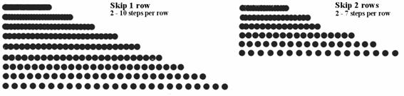
 ‘Ratchet’
was the Aeolian factory term for roll step rate, being the number of steps per
two inches. The best match for ‘42 ratchet’ perforation pattern is 10 steps per
row, which gives 21.5 rows per inch. This gives a copy about 2.4% shorter than
the original roll. To get a bridge at this resolution, a single perforation row
is omitted. As can be seen in the skip patterns diagram, the optimum step rate
for a punch-miss-punch pattern is probably 9 steps per row. With 10 steps the
bridge is a little too wide.
‘Ratchet’
was the Aeolian factory term for roll step rate, being the number of steps per
two inches. The best match for ‘42 ratchet’ perforation pattern is 10 steps per
row, which gives 21.5 rows per inch. This gives a copy about 2.4% shorter than
the original roll. To get a bridge at this resolution, a single perforation row
is omitted. As can be seen in the skip patterns diagram, the optimum step rate
for a punch-miss-punch pattern is probably 9 steps per row. With 10 steps the
bridge is a little too wide.
However, looking at another 42R roll that uses bridged slots, it can be seen that the copy and original rolls are fairly similar in appearance, with maximum bridge widths about the same in both (the copy being more consistent than the original but with fuzzier perforations). So, the 21.5 row per inch rate just about makes an acceptable match for the original roll.
Ideally, when the perforations are a little smaller, it would always be best to err on the slightly lower side to keep bridges about the right size. As can be seen in the table, the 47R and 63R best-match rates both give a slightly longer roll. 63R rolls use a double skip to create a bridge, and the 7-step rate gives over-width bridges: a 6-step rate would be safer but give rolls about 10% short. 47R rolls use single skip bridging, which at a 9-step rate gives ideal bridges: these rolls were originally perforated with smaller punches than Duo-Art rolls, so are a better fit to the Laguna machine.
This exercise has shown that although 215 steps per inch sounds very accurate, each step still represents about 14% of an original row, so there could be cases where the best match would still be 7% wrong, which would not really be acceptable. As it happens, there is a fairly close match to the common Aeolian rates. There are some easy fixes that can help here, such as half-stepping the paper drive (a cheap chip is available to do this).
Thoughts on using replica master rolls
Perforator designs vary widely. For the purpose of making replica rolls, the issues are their punch sizes and the step rate they can achieve. A traditional design would have a fixed punch set and mechanical drive, possibly with interchangeable gearing for the step rates to be produced. Modern recutting probably requires greater variety in the type of rolls that can be produced. A stepper-motor driven perforator can change its step rate via software to match the roll master being used, but needs very fine resolution to be able to match original perforator rates accurately.
The limiting factor for a perforator is how its punch sizes match those in the original roll. Bridge widths and inter-note gaps must remain within an acceptable range for the playback instrument to operate successfully, and bridges also need to be wide enough to perform their paper-strengthening function. While the Laguna perforator uses fairly small punches, many modern machines have over-sized punches (aiming to deliver more air to poorly-functioning players). Both approaches compromise the ability to replicate original roll perforation patterns at their original length while keeping the paper webbing within bounds.
The truly significant factor for judging a roll is the performance it gives, not the exact length of the roll: if the pattern of perforations is correct, the roll speed can be compensated to give perfect playback timing. This type of tempo compensation can be seen in different production runs of original rolls when different perforator designs were used. There are knock-on effects from varying the paper speed, such as differing buildup acceleration as the roll progresses (although this also arises if a copy of exact length is punched on paper of different thickness to the original). Frankly, these issues are irrelevant given the limited accuracy of most machines’ tempo control and the care taken to set it for playing a particular roll!
Conclusion
Although this is not the first time that roll images have been interpreted into a perforation matrix, it has been achieved here with relatively lightweight, low-specification equipment that is within the reach many enthusiasts equipped with fairly modest engineering and electronics skills. Earlier devices have tended to use expensive parts and far more complex construction to achieve the same results. The use of sophisticated software to analyse the scanned image has allowed substantial improvements to be made to the basic accuracy of the scanner, and now allows manufacturing faults in the roll to be corrected. Using the resulting master to operate a perforator has identified the qualities required to produce accurate copies of original rolls, and ways to work around the limitations of individual perforators. The approach of combining hardware and software has been demonstrated to achieve results well in advance of traditional approaches.